So one of the phases in my project is connecting the Raspberry Pi to a micro-controller that has many Pulse Width Modulation (PWM) signals. Since the Raspberry doesn’t have the number of PWM signals I need to control i’m going to do so through SPI. This post is the ‘how to’ on getting your SPI signals outputting from your Raspberry Pi. More blogs to come later to show you more details.
INSTALL
sudo apt-get update
sudo apt-get upgrade
SPI BACKGROUND
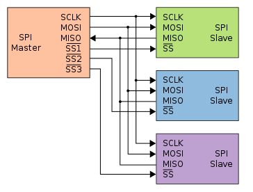
While that is updating lets talk a little bit of SPI background knowledge is needed in order to get this working. First off Serial Peripheral interface (SPI) is made up of 4 wires normally. It is a standard that was designed by Motorola for use with their micro controllers. If you’re interested in learning more about SPI i’ve added the Wikipedia link. Here is what a standard SPI setup looks like, multiple slaves is optional.
SS – Slave Select (Beagleboard community calles this Chip Select (CS))
MOSI – Master Out Slave In
MISO – Master In Slave Out
CLK – Clock

More INSTALL
sudo apt-get install git
Now lets download his tool and install change who has access to read/write the tool.
sudo wget http://goo.gl/1BOfJ -O /usr/bin/rpi-update
sudo chmod +x /usr/bin/rpi-update
Once this is done you can run it by calling the following command. (mine took a while).
sudo rpi-update
*NOTE – while I was doing this I ran out of space on my 4GB drive. I figured I wasn’t really low on space and when I checked it I found my windows tool originally only made me a 2GB partition. There are many ways to do this, but I used GPARTED to expand my space to the real 4GB. It’s a live CD…
SanDisk 4GB Extreme 3 SD Card w/Reader
So once the updates are all completed. I rebooted my Pi.
sudo shutdown -h now
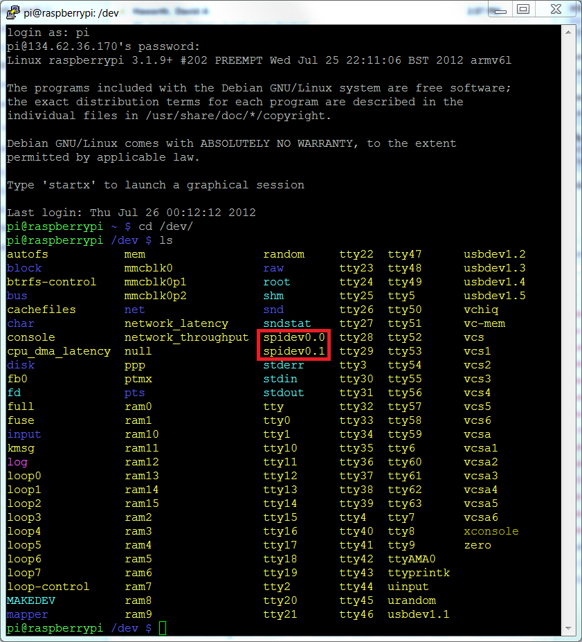
Unplug the power and plug it back in. And when I rebooted I went to my /dev/ directory and found my spidev devices!
The last part of this is to test the SPI signal. I’m going to download spidev_test.c
wget http://git.kernel.org/?p=linux/kernel/git/torvalds/linux.git;a=blob_plain;f=Documentation/spi/spidev_test.c -O spidev_test.c
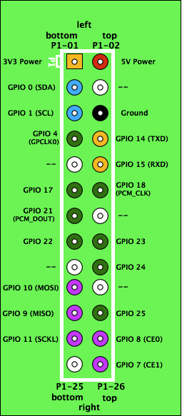
Next we want to short the MISO and MOSI pins. Located as GPIO 9 & GPIO 10 as seen below.
We want to edit the spidev_test.c file so it it uses the correct spidevice in our /dev/ folder.
nano spidev_test.c
scroll down and change the device to “spidev0.0” and then save it by pressing the Ctrl+O to save and Ctrl+X to exit. lets compile this thing and run it now.
gcc spidev_test.c
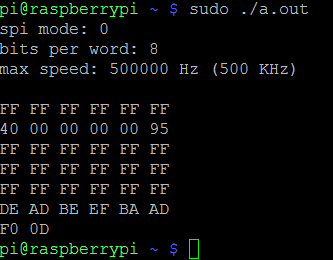
sudo ./a.out
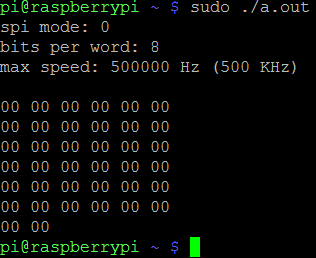
If you see this it’s working.
If you see this it’s not working.
For more information on how to control your SPI with python try checking out my post for how to do so on the beagleboard xm. Many have found it useful and i’m sure you will too. Python controlling SPI on the Beagleboard XM
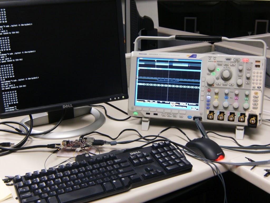
Above is a picture of my Tektronix Mixed Domain Oscilloscope (MDO) testing out a SPI signal on a Beagleboard XM. Great piece of test equipment!
Thanks for the Great post!
Excellent write-up. Two things:
1) You might mention you can opt to expand the roor partition from the raspi-config menu on the first boot (saves hassle later).
2) You should add a step after the rpi-update to comment out the blacklist spi-bcm2708 entry in /etc/modprobe.d/raspi-blacklist.conf to load the spi-bcm2708 module on boot. (Otherwise you don't see the spidev modules loaded after the reboot.)
Thanks for this helpful post. The command line to get spidev_test.c needs a bit of tweaking. Here's my version:
wget http://git.kernel.org/?p=linux/kernel/git/torvalds/linux.git;a=blob_plain;f=Documentation/spi/spidev_test.c -O spidev_test.c
Thanks for the update 🙂
Brian
My apologies for appearing to be nit-picking…
I think you still need to escape the semicolons in the command (see my line above).
Peter
Is it possible to have a SPI clock > 500khz?
Also, any one know how large the SPI hardware buffer is?
Instructions are clear and my spi is now available !
By the way, running 'raspi-config' can also be run at anytime later to expand your root partition.
Just Like to say thank you, got it working in no time
As of right now (Nov 26, 2012, 10:50AM EST) "sudo rpi-update" is failing with the error message:
/usr/bin/rpi-update: 1: /usr/bin/rpi-update: Syntax error: redirection unexpected
As far as I can tell, I got the rpi-update file as described in this page.
"file /usr/bin/rpi-update" reports
/usr/bin/rpi-update: HTML document, ISO-8059 text, with very long lines
ls -1 /usr/bin/rpi-update reports a 193705 byte file.
The problem with rpi-update is not a deal-breaker. Likely my Pi is new enough already. "sudo modprobe spi_bcm2708" creates the devices and spidev_test.c works as advertised. Many thanks for this post.
Excellent tutorial, nice and clear.
I notice the Raspberry Pi comes with the kernel module for the DS3234 RTC,
Any chance of showing how to get that wired in and the used as the RTC rather than NTP?
(as a real-world example of using SPI with the Raspberry Pi…)
modprobe spi_bcm2708 – this worked for the loop test
modprobe spidev — I had to do this aswell to get my SPI working with an external microcontroller
I actually had to do what you mentioned, thank you for the hint on uncommenting the module!
Many Thanks for your help from Germany. It was very usefull for me. Sorry for my poor english.
Best regards
Thomas
Can i install more devices for spi? 2 devices are not so much.
Thomas
I got this once too. I think I spelled the URL wrong.
It's possible to send 16 bits per word? I'm trying to change the file with not good results.
Thanks for the blacklist tip! I'm pretty green, so I had to go elsewhere to figure out HOW to do that…
$ sudo vi /etc/modprobe.d/raspi-blacklist.conf (to be able to view/edit the file)
press 'i' to be able to insert characters
add '#' in front of 'blacklist spi-bcm2708' to comment it out
press 'i' again to exit insert mode
exit the editor with ':wq'
There may be better/faster ways to do this, I'm just regurgitating. But that worked for me!
Yep, there's a better way. Instead of '$ sudo vi ' use the command '$ sudo nano' It's a way better editor.
Also, I hadn't changed my keyboard layout from 'gb' to 'us' when I tried this, and I got '£' instead of '#' when I tried to comment out that line. Like I said, I'm pretty green.
I have an issue with my CS signalfrom my RPi appearing as a clock with opposite polarity to my SCLK. I am calling the program using: sudo ./a.out -D /dev/spidev0.0
Is there another setting I have to change before I can connect to external devices?
You should be able too since SPI works on the grounds of the same MISO, MOSI and CLK lines but different CS/SS lines. When you use 0.0 or 0.1 SPI devices this should only be using the different CS/SS lines. If you want more than 2 devices you're out of luck for the raspberry pi.
Cheers,
Brian
I believe the CS line is active low by default. But you shouldn't be seeing it as a clock. How are you determining this is true? Make sure you're using the right pins on the board, and if you have access to an oscilloscope check it. Send me a picture if you can.
Cheers,
Brian
brian (dot) e (dot) hensley (at) gmail (dot) com
…. so what do we do if its not working? I'm very confused. Any suggestions?
Well lets define not working. Are you getting any SPI devices showing up in the /dev folder?
cheers,
Brian
Hi Brian! Thanks so much for the reply. I've worked through this whole tutorial and my output is all 0's instead of the decoded output of the spidev_test.c script. I do have the SPI devices in the /dev folder.
Hi Alanna!
If you see the SPI device in the /dev folder than that's most the battle. From here I would focus on making sure you have the correct pins (MISO & MOSI) pins connected on the board. Other than that make sure the script calls the correct spi device (hint: either 0.0 or 0.1 should work).
Cheers,
Brian
Hi Brian,
Thank you again for the fast response! I was not aware that I needed to wire the raspberry pi at all. Can you explain this further? What should I have wired exactly?
Thank You,
Alanna
Hi Alanna,
If you look back up at the green picture of the pins on the Raspberry Pi you'll notice pins 9 & 10 are the MISO and MOSI. This is the data out and data in pins. If you don't have those talking to another device or to each other than you won't see data coming back into your device.
I would recommend shorting those two pins together. After that your c program will work. eventually you'll have a SPI device connected and it will send data to and from the SPI stack.
Cheers,
Brian
OH MY GOSH! IT WORKED!!
Do you have any suggestions on where to look for a quick example of sending data from a GPIO output to go through the SPI?
Brian, your blog has been the most helpful with SPI that I've found so far and I've been doing a lot of researching trying understand all this. I just want to thank you!
Glad it worked for you Alanna!
My only example is for sending values through the SPI with python.
http://www.brianhensley.net/2012/02/python-controlling-spi-bus-on.html
Cheers,
Brian
Hi,
I have an android board with can spi, I want to know how can we get the details of the data which we send/write through socket to CAN-SPI.
I have a target side application and with that I am sending the data in bytes(a string data) to socket and which should straem in to CAN-SPI
any Idea?
The Chip Select (CS) line doesn't have to come from the SPI hardware. Any GPIO pin that isn't in use elsewhere for chip select as long as you only have one device on the SPI bus which has its chip select line pulled low.
The built in drivers only allow easy access to 2 devices but you could simply combine the SPI driver with your own GPIO code to manage more devices.
No reason the driver couldn't be modified to map more chipselects to the additional IO pins.
Keep in mind, devices like the Arduino don't even HAVE actual chip select lines when in master mode, you just set any other random pin you want thats tied to the SPI device you want to activate. All other GPIO tied to SPI devices are held high to prevent them from talking or listening.
SPI is a byte oriented interface. If you want 16 bits, you have to send two bytes yourself.
I have tested and the SPI is working up to 15 MHz = 15000 KHz. André
Do you have to compile a new kernel to get past > 500Khz ? I found the "max speed" setting in
arch/arm/machbc2708/bcm2708.c is 500Khz. Why is that set so low anyway? Why not set it to 32Khz in the Kernel and set it lower in a setting that is manageable without editing the kernel? Compiling a kernel proves to be beyond me.
No, i have changed the speed setting in the above spidev_test.c program like
static uint32_t speed = 15000000;
And then tested with the same program.
André
Great post!!!! 😀
It seems Brian's method for installing the SPI drivers doesn't set the SPI speed in the kernel as Occidentalis does (which is good). I am using Adafruit's light painting python script to process images and output to a LPD8806 LED strip http://learn.adafruit.com/light-painting-with-raspberry-pi/software and Brian's method to install the drivers. It works but I can't figure out how to set the SPI speed within a Python script. I just rebooted our website http://stargateeggbeater.com/ spherical POV display
DEAD BEEF BAAD F00D. It works!
Thanks, brother, for the most direct and successful Pi SPI lesson. Well done.
A ZBasic ZX24 slave will be talking with the Pi before the sun sets. Thanks.
Tom
Great write-up. Other than the non-escaped semi-colons in the last wget, it worked as a charm.
Thanks,
/Bo
Is it possible to use PIN 10 as MOSI while still using pin 9 as a GPIO pin if you don't need master input. I imagine the answer is No. But I'm hoping it might be "Yes"?
Also I assume that SS or CS isn't part of the driver but rather tied directly to ground or if you want to do it with the Pi you have to drive one of the GPIO pins is that correct?
Thanx for the tutorial but…
after the job in /dev dir no spidev0.0 & spidev0.1
so you must do:
sudo nano /etc/modprobe.d/raspi-blacklist.conf
add # before the 3rd line
$ cat /etc/modprobe.d/raspi-blacklist.conf
# blacklist spi and i2c by default (many users don't need them)
#blacklist spi-bcm2708
blacklist i2c-bcm2708
save, exit & reboot
that's it!
Wow … thanks for this. Got me pointed in the right direction.
(With the newest wheezy all I had to do was uncomment the line in the black list and reboot.)
Andre
Hi Andrea,
Yes from what i'm seeing on many builds of the OS it is getting simpler. All that is needed is for a couple lines to be commented or uncommented. Like I did for my beagleboard xm SPI tutorial i'll have to go revisit a new download and confirm your findings and update the tutrorial. Its just a matter of when I get time to do it. Thanks for the information though!
Cheers,
Brian
Thanks for sharing this effective article. I like the Idea. Great thinking! There is wonderful about "Getting SPI working on the Raspberry Pi". I am impressed by the quality of information on this website. There are a lot of good quality resources here. I am sure I will visit this place again soon. You can find some information with it.
I want to know how to connect between the raspberry pi and atmega16 using SPI connection. I want an image for the connection and the code will be used. Please help me.
Hello Anonymous,
Please check my other blog posts. As I have one using a SPI connection to a ATMEGA64 controller for my robot project.
http://www.brianhensley.net/2013/03/raspberry-pi-robot-wii-remote-phase-1.html
Cheers,
Brian
Thanks alot Brian for replying quickly. But I want the raspberry pi to be the receiver of data from the atmega, and the atmega to be the sender of data. Therefore, how can you help me in order to do this?. Can I use atmega16 rather that atmega64?. I'm waiting for your replying.
Hi Brian,
i have read your tutorial and wanted to test it on my own.
i have connected the miso and mosi of the raspberry pi, commented out the spi_bcm2708 in the blacklisted-file but the spider_test is not working…
lsmod shows, that spi_bcm2708 is loaded…
Do you have any ideas, what could be wrong?
Hi Brian,
I have connected the pi as you have shown in your video above and I ran the program. However the output I am getting is as follows
"spi mode: 0
bits per word: 8
max speed: 500000 Hz (500 Khz)"
I am not getting the Hex values that you had got in your video. Not even the "00 00 00 00 00 00 00…" error message that tells you that it isn't working.
I edited my /etc/modules to run the spidev0.0 and spidev0.1 to run at boot itself. I have the MOSI and MISO pins shorted as well.
What could have gone wrong?
Is it possible to put the Pi in SPI Slave mode to snoop on SPI traffic?
I have an SPI bus at 1mghz that I need to record the data from, I simply want to dump all data to a file for later review but have NO idea how to do this, can the Pi even do SPI slave?
Hi Brian,
I have the same problem Andrea (May 8 2013) had in that I cannot see spidev0.0 or spidev0.1 when I list what is in the dev directory but after I have commented out the blacklist entry in the file and rebooted.
Any ideas.
Thanks for the info. It helped me to use my Pi to dump the contents of a 93c46 eeprom. The part I kept missing though was you need to send dummy bytes to the device in order to get the data you just requested back. So its "Start bit", "Read opcode""address", "0x0 byte", "0x0 byte", "0x0 byte" will return the 16 bit address you just requested in the 3rd, 4th and 5th response bytes (as it sends back a dummy 0 bit first). Here is the python code I used:
#93c46 dump routine
import spidev
import time
spi = spidev.SpiDev()
spi.open(0,0)
#93c46 chip select is high rather than low
spi.cshigh = True
#Combine the start bit and first bit of the read instruction into one
#to be sent as first byte. Second bit (0) of read instruction will be
#provided along with address to read in second byte
start_read = 0b11
count = 0
while (count < 64):
#shift the address to the left so the dummy 0 bit that comes back is
#part of the address byte we're sending. This saves having to do bit
#twiddling with the response (to ignore the dummy 0).
resp = spi.xfer2([start_read, count << 1, 0x0, 0x0])
#convert the two returned bytes into hex and print them
ch1 = "%x" % resp[2]
ch2 = "%x" % resp[3]
print count, ":", ch1.zfill(2), ch2.zfill(2)
count = count + 1
time.sleep(.1)
Thanks again
JC
might be possible, you would have to write your own module/drivers, but the hardware should be able to do both. You just have to write code on the Pi that can handle taking in data in normal SPI format.
I did a similar concept for my robot micro-controller project, I dumped extra bits into it so I could get all my data back to verify directions and speed that I was controlling. Glad you got it all working.
Cheers,
Brian
I used the process described by Brian and all worked fine and really useful. I need to gain access to the SPI with python on my Rpi so have installed python-dev and setup.py etc… However when I run a basic python test script I get IOError: [Errno 13] Permission denied. I assume this is because spidev0.0 only has root access. As a user how do I get access to spidev0.0?
Hello Aim,
First make sure you can see the spidev0.0 in your Dev folder. Next make sure you have something connected to the port. Then when you run your script make sure you use the sudo command. I have a few other spi posts and examples on this blog that I recommend you check out as well…
Cheers,
Brian
This comment has been removed by the author.
Thanks Brian, am I right in thinking that if I try the handshaking scenario you describe in your original blog where the MISO and MOSI pins are shorted it would not work?
I recommend in my posts that you short the pins together so data out will transfer to data in… then when you run the code it will display the received code correctly. If you don't short the pins together nothing will happen…
Cheers,
Brian
That's what I feared, still no joy then. I'm still getting the permission denied error message. When I run it using sudo ,/filename.py I get no errors in the command window. If I run it through IDLE i get the permission denied error. Because of spidev would it only work through sudo anyway and as only sudo has permission for spidev0.0/0.1 it wouldn't run as myuser in IDLE?
I think I have sorted it after a bit of reading that I should have done before I started bothering you. Thanks for your help though and for a very useful blog.
Regards
Hi Brian,
can you help with interfacing CAN controller through spi pins of raspberry pi with clear steps.i referred forums it doesnt help me out.tell me out with steps.
Hi Brian,
Its very interesting to see ur blog. I did Getting started SPI working on my R-pi as per ur steps its working fine. Now i planned to interface CAN in my R-pi SPI port in GPIO.
Can you help me with interfacing CAN controller through spi pins of raspberry pi with clear steps.i referred forums it doesn't help me out.tell me out with steps.
After i did all steps mentioned from the forums-
http://www.raspberrypi.org/phpBB3/viewtopic.php?f=44&t=7027&start=150
Im getting like " Cannot find device "can0" ".
Pls provide solution for my problem
Thanks in advance. 🙂
Regards
Abi..
Hi,
Did yu make the SPI working with an external controller.please help me on this.
Thanks.
Hi I followed your post, and the spidev0.0 and spidev0.1 are not appearing in my dev/ files, any idea why?
Mnay thanks
Gareth
you should do all rpi updates,shutdown and then lists the device..
Hi Brian,
Do you know if spidev on the PI can be modified to use > 8 bits per word? I'm trying to communicate with my SPI device (TFT display with ILI9340) and I'm seeing the message is sent over SPI (ioctl doesn't report any errors). However, the TFT display doesn't seem to respond to any of the messages. I'm not sure how to debug as I don't have any equipment and I only have a software background so using a scope is out of the question. Do you know if there needs to be any kernel mods to have spidev function correctly?
I'm basically trying to write a user-space program to interface with a SPI device. I've posted in the PI forums and the Adafruit ones (since they are the maker of the TFT device i'm trying to use), but nothing productive came out of it… 🙁
http://www.raspberrypi.org/phpBB3/viewtopic.php?f=33&t=61318
http://forums.adafruit.com/viewtopic.php?f=47&t=45450
Any ideas or suggestions? or examples 😉 ?
Brian,
I followed your instructions, and both spi devices appear in /dev. I tried spi_test.c which appears to work with the loopback and not without loopback connected. But it works the same when using eithe dev 0.0 or 0.1.
spi_test.c uses ioctl with one tranfer struct holding the tx & rx bfr addresses. When I try to use ioctl with two xfer structs (one for tx, and the other for the rx), the app does not work.
Also, I have tried the other spi demo program which uses the write ( … ) & read( … ) fumcs. This also doesn't work as expected. The tx appears to work properly; the read() receives the number of bytes requested rd_bfr, but the rd_bfr which had been initialized to a known pattern was all zeros after the read. I thought that I should see the the characters sent by the write().
Any suggestions would be appreciated.
Thanks,
George
Hi Brian,
Thanks for your clear tutorial on SPI. However, I'm stuck with this problem.
I can see spidev0.0 and spidev0.1 under /dev, but when I run spidev_test.c I receive only zeroes. I have connected the MOSI and MISO pins with a female jumper cable. The only unusual thing compared to your tutorial is that "/etc/modprobe.d/raspi-blacklist.conf" is completely empty (I've installed Raspbmc).
What could be the problem?
Jim
its defined as _u64 in spidev.h
Hi Brian,
(So I tried posting this question a few minutes ago but it doesn't seem to have worked so I'm trying again. Sorry if there's a repeat)
So I tried your tutorial, and I have the spidev0.0 and 0.1 in /dev/, but when I run the script I just get out "can't open device: No such file or directory". I don't know how to troubleshoot this and I haven't seen this error anywhere else on the web in regard to the RPi doing SPI. Do you know what this might be?
Thanks for any help, and thanks for the tutorial!
Jimmy
Nevermind, I figured it out. I only changed the device to spidev0.0 in one place, not both. Thanks!
Thanks. But, be aware that if you do this and get a new version of spidev_test.c, you will wind up with a bunch of compiler errors about undefined constants. The newer version uses constants that the Pi's include file does not have. Make sure you get an old version of spidev_test.c!!!
can't compile this:
pi@raspberrypi /tmp $ gcc spidev_test.c
spidev_test.c: In function ‘transfer’:
spidev_test.c:60:13: error: ‘SPI_TX_QUAD’ undeclared (first use in this function)
spidev_test.c:60:13: note: each undeclared identifier is reported only once for each function it appears in
spidev_test.c:61:5: error: ‘struct spi_ioc_transfer’ has no member named ‘tx_nbits’
spidev_test.c:62:18: error: ‘SPI_TX_DUAL’ undeclared (first use in this function)
spidev_test.c:63:5: error: ‘struct spi_ioc_transfer’ has no member named ‘tx_nbits’
spidev_test.c:64:13: error: ‘SPI_RX_QUAD’ undeclared (first use in this function)
spidev_test.c:65:5: error: ‘struct spi_ioc_transfer’ has no member named ‘rx_nbits’
spidev_test.c:66:18: error: ‘SPI_RX_DUAL’ undeclared (first use in this function)
spidev_test.c:67:5: error: ‘struct spi_ioc_transfer’ has no member named ‘rx_nbits’
spidev_test.c: In function ‘parse_opts’:
spidev_test.c:172:12: error: ‘SPI_TX_DUAL’ undeclared (first use in this function)
spidev_test.c:175:12: error: ‘SPI_TX_QUAD’ undeclared (first use in this function)
spidev_test.c:184:12: error: ‘SPI_RX_DUAL’ undeclared (first use in this function)
spidev_test.c:186:12: error: ‘SPI_RX_QUAD’ undeclared (first use in this function)
spidev_test.c: In function ‘main’:
spidev_test.c:204:18: error: ‘SPI_IOC_WR_MODE32’ undeclared (first use in this function)
spidev_test.c:208:18: error: ‘SPI_IOC_RD_MODE32’ undeclared (first use in this function)
Hello Brian.
As part of a school project, I have to connect an accelerometer and a gyroscope to a raspberry pi. Apparently I have to use the CS (chip select) and code in python but I have no idea how to do that. Can you help me out please?
I was also having the same problem as the poster on 21 May 2014. It looks like the version of spidev_test.c mentioned in this article is no longer correct. Take a look at this thread: http://www.raspberrypi.org/forums/viewtopic.php?t=75886&p=542813 The version pointed to there compiled and ran just fine for me. HTH
Yes, this is a bit late but I read this article late:)
The Python wrapper to Rpi.GPIO named RPIO currently 0.10.0 supports PWM down to 10us and with up to 15 channels using DMA. I am testing the RPIO module and the output signals look very good. The neat part about using the BCM hardware DMA is that you can assign the PWM channels as you wish ans not to a dedicated pin. Great for Servo control.
Only issue I see with RPIO is lack of support to configure the number of PWM periods. Currenly it simply runs continuously until given a stop command. I you wanted to send 3 PWM periods you would have to add a blocking sleep delay approximately equal to those periods combined.
Thank you Brian
Hello Brian, great write up. I have on issue, when i run sudo ./a.out i get the following error:
sudo: ./a.out: command not found
Do you know what I am doing wrong? Thank you in advance.
I came across this post looking for a fix to RPI problems with the more recent kernel upgrade (3.18)
There is one other step to the above that you need to do:
Add “dtparam=spi=on” to your /boot/config.txt and reboot.
https://raspberrypi.stackexchange.com/questions/27073/firmware-3-18-x-breaks-i2c-spi-audio-lirc-1-wire-e-g-dev-i2c-1-no-such-f?newreg=d5f1e383852548aa9ec8158b694371f9
http://www.raspberrypi.org/forums/viewtopic.php?p=675658#p675658
Thank you Brian for this post
I need some help pleae. I don't understand which part I have to modify after I have enter :
nano spidev_test.c
Fabien
Hello Brian. Could you please just post the spidev_test.c code that you know is working so we don't have to play "Go Fish" with Google an hope we stumble across the right version?
Thanks
Hi PiGuy,
The code is actually listed on this page, you just have to click on the link 'spidev_test.c' then follow my instructions for compiling and running it. Make sure you connect the pins on your board to test it.
Cheers,
Brian
Hello Fabien,
Download the 'spidev_test.c' file and load it to your Pi, then open and edit it with the 'nano' command. Then follow my instructions for compiling it. Make sure the pins are crossed on the board so data can be brought back input.
Cheers,
Brian
Make sure you move into the directory that your file was compiled in, then run it.
Cheers,
Brian
I needed to send some very low frequency SPI pulses (thru optoisolators) and was at a loss until I found your post (WiringPi has a low speed limit). Thank you very much!
Very clear instructions. Got mine working after failing with the standard instructions.
Thanks a lot Sir.
Clear instructions. Thanks a lot sir.
The current standard instructions need to highlight the gotcha regarding the dev not appearing.
Hi Brian, Thank you for your beautiful blog. may I know if you have experince in flashing a Flash Winbond 1.8V W25Q64.W with Raspberry Pi ? I tried to unbrick a Windows tablet using flashrom. But I had trouble getting a consistent firmware dump. I also used a logic level shifter from Sparkfun to shift the 3.3V SPI pins down to 1.8V.
When I go to compile spidev_test.c I get a lot of errors saying that SPI_RX_QUAD undeclared, SPI_RX_DUAL undeclared, and so on for many of the SPI objects.
Why would this be?
For anyone else having problems on a B+, I needed the old spidev_test.c file, which does not use the pre-declared definitions in headers, such as – SPI_TX_QUAD, SPI_TX_DUAL, etc. If you are getting the same errors that I was, these definitions give you problems. You can find the old code in the link below. It worked like a charm for me!
https://git.kernel.org/cgit/linux/kernel/git/torvalds/linux.git/plain/Documentation/spi/spidev_test.c?id=95b1ed2ac7ffe3205afc6f5a20320fbdb984da92
"can't compile this:
pi@raspberrypi /tmp $ gcc spidev_test.c
spidev_test.c: In function ‘transfer’:
spidev_test.c:60:13: error: ‘SPI_TX_QUAD’ undeclared (first use in this function)…"
I fixed this by grabbing the newest version of "spidev.h" from github, then placing it in the same directory as "spidev_test.c", then editing "spidev_test.c" so it points to the local "spidev.h" and not the "linux/spi/spidev.h" … like this:
//#include
#include "spidev.h"
Odds are good that will compile.
Note: you might want to make a copy of the old "spidev.h" just in case it gets overwritten.
pi@raspberrypi:~/dev/spitest $ ls /dev/*spi*
/dev/spidev0.0 /dev/spidev0.1
MOSI is tied to MISO. Do any other pins need setting?
Edited torvalds spidev_test.c with:
static const char *device = "/dev/spidev0.0";
Results:
spi mode: 0x0
bits per word: 8
max speed: 500000 Hz (500 KHz)
RX | FF FF FF FF FF FF FF FF FF FF FF FF FF FF FF FF FF FF FF FF FF FF FF FF FF FF FF FF FF FF FF FF | …………………………..
Does this mean problem with Raspberry Pi SPI? What else to try or check?
Mine is working now. Thanks a lot!
Is there a difference between spidev (3.2) and the library 'python-periphery', or the 'py-libbcm2835' library? They all seem to do spi, however not sure if they have different applications or if they are just deprecated libraries?
Interestingly, the spidev documentation says you can set the number of bits per word(transfer) , 8..16, however according to the pi documentation, the spi peripheral connected to the header only supports 8/9! So perhaps spidev is a generic driver whose functionality may or may not be fully supported by the rpi?
BTW, doesn't a python list ([0x90,0,0,0,0]) consist of ints and not bytes? Does the driver take this into account and convert it to 8-bit bytes before sending?
Usually I don’t read article on blogs, however I wish to say that this write-up
very forced me to check out and do so! Your writing style has been surprised me.
Thanks, very nice article.
Maybe a little late, but someone posted they got spi_mode, bits per word and max speed but didn’t get the hex bytes.
Try
./a.out -v
Thanks for the article – it has helped with debugging my problem with flashrom.